
Paperis Articles
Compression and Tension — Stones Set Against Each Other, a Sagging Clothesline
The parts of a building are mostly squeezed shorter or pulled longer, and a beam supported at both ends, when it bends, is squeezed on top and pulled underneath. So the shape of a structure carries a choice of where to resist by pushing and where by pulling.
Your field's papers, as audio
Pick your fields and journals — Paperis summarizes the key papers and turns them into audio. Listen on your commute.
Start Paperis free →Compression and Tension — Stones Set Against Each Other, a Sagging Clothesline
A Sagging Rope and Mating Stones
When you hang a wet blanket on a clothesline strung across a yard, the line sags downward from the middle. The line carries the weight of the blanket all the way to the stakes at both ends and hangs it there. The line cannot lift the blanket upward with that line. A rope does work only when it is pulled.
An old stone bridge endures the other way. You merely stack stones in a curve, and people and carts pass over it. The stones stand by pushing against each other.
Parts inside a building usually experience one of these two, or experience both at once. This article follows what gets compressed and what gets pulled, how materials change when they receive that force, and how the choice of "where to push and where to pull" is contained in the shape of a building. The guides are two: the mating stones that endure by being pushed, and the sagging clothesline that endures by being pulled.
Pressed Shorter, Pulled Longer
When you sit in a chair, the chair legs are pressed by your body weight and become shorter by an amount you cannot see. Unnoticeable as it may be, an object that receives a force changes its shape, if even a little (OpenStax University Physics Volume 1 12.3). Deformation is when an object's length or shape changes upon receiving a force.
Let us move to a building. Load is the general term for the weight and forces that a building receives. A structure is the framework that carries the loads a building receives down to the ground.
The representative parts of that framework are beams and columns. A beam is the part laid horizontally that receives the weight above it, and a column is the part standing vertically that sends that weight down. The path by which a load travels down to the ground is followed in "Loads and Load Paths — A Child on Your Shoulders, Weight That Travels Down to Your Soles".
Let us isolate a single column. From above, the weight above it presses down, and from below, the support pushes up with the same magnitude. Because the two forces have the same magnitude and opposite directions, the column does not budge. Equilibrium is a state in which the forces acting on an object balance each other out, so that the object neither starts to move nor starts to rotate. (OpenStax University Physics Volume 1 12.1) A column in equilibrium is also caught between two forces, being pressed and shortened by that amount. Even when all the forces acting on an object add up to zero, opposing pairs of forces change that object's length (OpenStax University Physics Volume 1 12.3). A building standing still is also receiving forces.
Depending on which direction the opposing two forces push the object, their names diverge. Being pushed and tending to shorten is called compression, and being pulled and tending to lengthen is called tension. In both cases, the force acts along the longitudinal direction of the object, and the only difference is the direction (OpenStax University Physics Volume 1 12.3). Columns and stones set against each other receive compression, and clotheslines and ropes hanging lights from ceilings receive tension. There are also forces that twist an object or push it layer by layer out of alignment (OpenStax University Physics Volume 1 12.3), but this article follows only pressing and pulling.
Same Force, Narrow Space
If you hang a heavy load from a single thin thread, the thread snaps. If you double up the same thread into several strands, it bears the same load. The weight of the load remains the same, and only the area of the thread sharing that weight has increased.
Stress is the value obtained by dividing the force a material receives by the area receiving that force, and even the same force becomes greater the narrower the space in which it is received (OpenStax University Physics Volume 1 12.3). It is calculated in the same way for compression, where it is pushed, and tension, where it is pulled (OpenStax University Physics Volume 1 12.3). A material breaks when its stress reaches a certain value (OpenStax University Physics Volume 1 12.4). This is why multiple strands of thread survived the same load.
We will not calculate stress in this article. There is only one thing to take away. You cannot tell how much that part is suffering by looking at the weight alone, and you must look together at how wide an area receives that weight.
Returning Deformation, Remaining Deformation
If you slightly bend the end of a wire coat hanger and let go, it returns to its original place. If you bend it hard, it stays bent. The same wire shows both behaviors.
Elasticity is the property where an object whose shape has been changed by a force returns to its original shape when the force is removed, and plasticity is the property where the changed shape remains even after the force is removed. Somewhere between when you bend the hanger slightly and when you bend it hard lies the crossing point. The elastic limit is the stress below which the material returns when the force is removed, and above which the changed shape begins to remain. This point differs for each material and has some width rather than being a single value drawn with a knife (OpenStax University Physics Volume 1 12.4).
What happens after crossing that point also differs by material (OpenStax University Physics Volume 1 12.4). There are materials that bend and stretch much further like a coat hanger before breaking, and materials that barely stretch at all before suddenly snapping. Which material belongs to which side is covered in "Building Materials — The Chalk That Snaps, the Paper Clip That Bends".
Then, is a material that does not easily deform under the same force a material that lasts a long time? How much a material deforms when receiving the same force varies by material (OpenStax University Physics Volume 1 12.3), and the stress at which it breaks is also separate for each material (OpenStax University Physics Volume 1 12.4). The former is how stiff it is, and the latter is the limit it can endure. A material that does not easily deform and a material that breaks later are not the same thing.
The Bending Beam: Stone on Top, Clothesline Below
You can try this with a single kitchen sponge. Draw several vertical lines in a row on the side of a long sponge with a pen at even intervals. Rest both ends on two fingers and press down on the middle from above so the sponge bends downward. At that time, the gaps between the lines narrow on the top side, and the gaps between the lines widen on the bottom side.
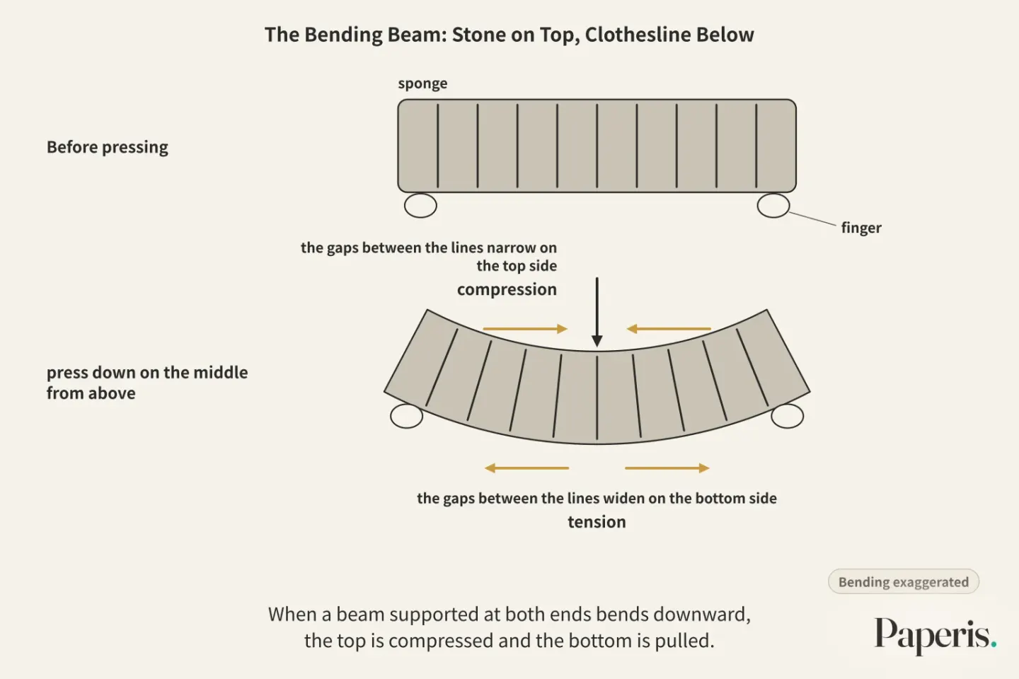
Bending is when a long object curves like a bow from a force received from the side. A beam bends under the weight received from above. When a beam supported at both ends bends downward, the top is compressed and the bottom is pulled (OpenStax University Physics Volume 1 12.3). Put simply, the top of the beam handles compression like stacked stones, and the bottom handles tension like a clothesline. A single beam contains both stone and rope together.
Therefore, in a beam, which force the material is weak against dictates where it will fail first. Concrete is very strong against being pushed and very weak against being pulled. So, concrete beams are reinforced by placing rebar (steel rods) on the side that gets pulled (DOI: 10.1201/9781351027700-18). The properties of concrete and steel are continued in "Building Materials — The Chalk That Snaps, the Paper Clip That Bends". There is also a more advanced method. Before the load pulls, the place that will be pulled is pressed down in advance. Then the pull that occurs later cancels out the compression put in beforehand (DOI: 10.1201/9781351027700-18).
The picture that the top is compressed and the bottom is pulled applies to beams of ordinary proportions. In a study examining very short reinforced concrete beams connecting walls in multi-story buildings where the height is small compared to their length, after diagonal cracks formed, the way internal forces settled differed significantly from beams of ordinary proportions, so that rebar in locations expected to be in compression were actually pulled instead (DOI: 10.1061/jsdeag.0002848).
Long and Thin Means Bending Sideways
Try standing a single dry strand of spaghetti upright on a table and pressing down on it with your finger from above. Instead of shortening straight down, the strand bows sideways like an arch and then snaps. A short-broken piece stands firm against the same hand pressure.
Buckling is when a long and thin object pressed in the lengthwise direction bends sideways instead of shortening straight. You press, and bending happens. Buckling is primarily an issue dealt with in thin or slender structures like columns or frameworks (DOI: 10.1002/1521-4001(200011)80:11/12<709::aid-zamm709>3.0.co;2-9). The sight of a column being pressed and bending sideways was noted down by medieval and Renaissance scholars as well, but those observations did not lead to uncovering the reasons behind it. Among them, Leonardo da Vinci came closest to the nature of the problem and left behind a few tentative rules, but they remained in his personal notes (DOI: 10.1590/s1679-78252011000100005).
Buckling depends on shape as much as it does on material. Actual columns can be bent ever so slightly from the beginning, so methods to take that small curvature into account appeared early on (DOI: 10.1061/9780784415832.ch2). One theoretical study (preprint, not peer-reviewed) calculated that even if the height, material, and amount of material used are the same, the weight a column can support varies depending on how its thickness is distributed between top and bottom (DOI: 10.2139/ssrn.6671070).
In columns built by stacking stones, tension can be hidden within the compression. When a weight rests heavily off-center from the middle of the column, one side of the column goes into tension and cracks (DOI: 10.1556/096.2023.00095). Whether a column holds up depends on how hard the material is, along with how long and thin it is, how straight it is, and where the weight rests.
An Arch That Stands Just by Being Pressed
We return to the stone bridge. The joints between the fitted stones barely hold any pulling force. A study that calculated stone arch bridges assumed the material could not take any pull, and the results largely matched large-scale experiments (DOI: 10.70803/001c.140428).
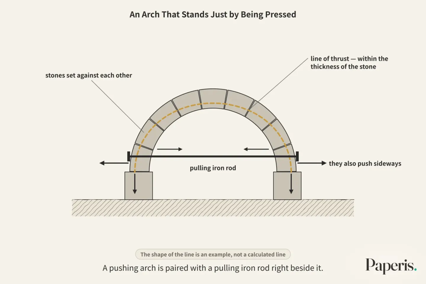
An arch is a structure that crosses a gap in an upwardly curved shape, holding itself up by pushing the received weight down to both sides. The weight passes from stone to stone as a push, going all the way down to the two feet. The line of thrust is the line connecting where the pushing force received by the arch passes as it goes down. This idea has deep roots (DOI: 10.3390/encyclopedia6030057), and in the theory dealing with stone-stacked structures, if one can find even a single line of thrust—among those that balance the received weight—that stays within the thickness of the stone, the arch is considered to hold (DOI: 10.1515/cls-2021-0003).
In this theory, the safety of a stone arch is a matter of shape (DOI: 10.1061/(asce)0733-9445(1995)121:7(1045)). In most stone arches, the stress is very low, meaning collapse does not happen because the material breaks (DOI: 10.1016/j.mex.2019.05.033). The appearance of a collapse is more like several joints turning like hinges so the arch turns into a bundle of moving pieces, rather than the stones being crushed (DOI: 10.1016/j.softx.2018.05.006). In an arch, shape comes before how hard the material is.
This picture also has its limits. While this theory is immensely useful for understanding arches, it has limits when used to evaluate real buildings. Real stone and mortar do not always behave as simply as the assumptions dictate, and vaults can experience three-dimensional effects that a flat drawing cannot fully capture. Other methods, such as three-dimensional computer models, have also been confirmed to be useful alongside this theory (DOI: 10.1002/pse.84). In one computer model that followed stone bridges all the way to collapse, how well the material could withstand a pull played a major role in the collapse pattern among the material properties examined, and this model was tuned to fit the results of collapse experiments on five full-scale bridges in the UK (DOI: 10.1680/ab.20481.0017). The statement "stone cannot take any pull at all" is a simplified assumption made for calculation (DOI: 10.1002/pse.84).
Arches do not only push down; they also push sideways. That is why old stone buildings sometimes have iron rods stretched across to catch the outward-pushing force of arches and vaults (DOI: 10.1201/9781315616995-175). A pushing arch is paired with a pulling iron rod right beside it. How the flying buttress of a Gothic cathedral transfers the pushing force of a high ceiling down to the foundation is one of the classic subjects in guidebooks dealing with old stone buildings (DOI: 10.1017/cbo9781107050310). Arches are also vulnerable to their feet spreading sideways. In computer model experiments, stone arches and vaults collapsed with much less movement when their supports spread sideways than when the supports sank downward (DOI: 10.1080/15583058.2014.923953).
Domes, which are stone-stacked vaulted roofs, also mostly stand by a pushing force. Yet many such domes experience a pull trying to spread them outward along their lower perimeter, usually resulting in vertical cracks running from top to bottom. That is why many domes are reinforced by wrapping a band made of steel or fiber around the perimeter (DOI: 10.4028/www.scientific.net/amm.865.397). Even within a pushing shape, there is a distinct place responsible for handling the pull.
A Rope That Survives Solely by Pulling
Let us return to the clothesline. If you hang more blankets on it, the line sags further, and the stakes at both ends are pulled inward by the line. You cannot support anything by pushing a rope.
A cable is a thin, tough rope, a member that experiences only pulling forces and cannot handle pushing forces. A rope cannot withstand being pressed or bent, and it changes shape depending on the load placed upon it (DOI: 10.1017/cbo9780511529665.006). Cables and arches are partners standing at opposite ends. While an arch arches upward and experiences only compression, a cable sags downward and experiences only tension. Just as the two feet of an arch push outward, the two ends of a cable pull inward.
This partnership extends to their shapes as well. If you flip the sagging shape of a light rope with a weight hung on it upside down, you get the shape of an arch that bears the same weight solely through compressive forces. Robert Hooke put forward this idea in 1675 as a Latin anagram, and the solution was revealed only after his death. This idea of the "hanging chain" was also used in the dome of St. Paul's Cathedral in London, designed by Christopher Wren (DOI: 10.1098/rsnr.1998.0033). The method of finding the shapes of arches and vaults by hanging ropes continued to be used thereafter, extending all the way to the stone vaults designed by Gaudi in Barcelona (DOI: 10.1002/9783433609613.ch3).
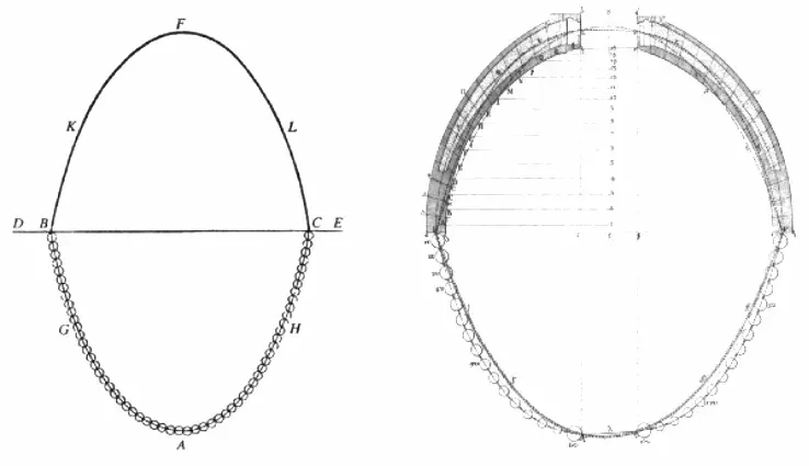
Poleni's drawing of Hooke's hanging-chain analogy for an arch; the dome section on the right is St. Peter's Basilica in Rome · Giovanni Poleni, 1748 · Wikimedia Commons (public domain)
When weaving wide roofs with cable nets or pulling tensioned membrane covers taut like fabric, computational methods are used to find the shapes of the ropes and membranes (DOI: 10.1260/0266351991494722).
There are also frameworks woven primarily from two things: pressing rods and pulling ropes. Such frameworks, pre-tensioned in advance, maintain their own shape, and their uses are expanding into architecture, engineering, and robotics (DOI: 10.3390/app13158669). The rods handle only compression, while the ropes handle only tension.
Shape Splits Force
We build two things from the same stone. If we lay the stone horizontally to use it as a beam, the underside of the bending beam is pulled (OpenStax University Physics Volume 1 12.3). If we fit the same stones into a circle to build an arch, the weight travels through compression inside the stones and down to both feet (DOI: 10.1515/cls-2021-0003). The material is the same and only the shape differs, yet the kind of force the stone experiences changes.
Choosing a hard material alone does not make a sturdy structure. A thin, long column bends sideways, a stone arch usually collapses because of its shape rather than the material, and a material weak to pulling reveals its weakness when placed in a spot where it is pulled. Therefore, designing a structure is also about deciding “where to let it endure by pressing and where by pulling”. The steel bars beneath a concrete beam, the iron rods beside an arch, the band around a dome, and a framework woven from rods and strings are all shapes that make those choices visible.
The abutted stones and the sagging clothesline are merely guides that show the two forces apart. Real stone also withstands pulling a little, and the "stone" and "string" inside a beam are not placed separately but connected as a single mass. The guide is only useful up to the point of separating the directions of force.
Where to Look Further
What force itself is and how force moves objects is covered in "Force and Motion — A Swinging Strap, a Body That Keeps Going". The reason a material stretches and returns depends on the very small structures that make up the material (OpenStax University Physics Volume 1 12.4), and the way atoms hold onto each other continues in "Chemical Bonds — A Rope Held Together, a Rope Pulled to One Side".
Other parts of this series also follow from this article. The path that a load takes from the roof down to the ground is followed by "Loads and Load Paths — A Child on Your Shoulders, Weight That Travels Down to Your Soles", and the story of choosing concrete, steel, and wood by the types of forces they receive is followed by "Building Materials — The Chalk That Snaps, the Paper Clip That Bends". The forces that push a building sideways are covered by "Wind and Earthquakes — Wind Pushing at the Side, Jelly Wobbling with Its Plate", and the cracks and rust that form in old buildings are covered by "Aging and Collapse — Rust That Swells from Within, Neighbor Columns That Take Up the Weight".
Source Papers
- "University Physics Volume 1 — 12.3 Stress, Strain, and Elastic Modulus" (2016) — OpenStax University Physics Volume 1 12.3 — Deformation occurs even under tiny forces, stress is force per unit area, tension and compression are opposing forces along the length (the length changes even if the net force is zero), and a supported, sagging object experiences top compression and bottom tension together.
- "University Physics Volume 1 — 12.4 Elasticity and Plasticity" (2016) — OpenStax University Physics Volume 1 12.4 — Elasticity is the property of returning to original form when a load is removed, exceeding the elastic limit leaves permanent deformation (plasticity) leading up to the fracture point, these limits are ranges rather than single points, and behavior past the limit varies by material.
- "Pre-Stressed Concrete Structures" (2019) — DOI: 10.1201/9781351027700-18 — Concrete is very strong in compression and very weak in tension, so the tensile side is reinforced with steel, and pre-compressing the tensile region cancels out later tensile stress.
- "Coupling Beams of Reinforced Concrete Shear Walls" (1971) — DOI: 10.1061/jsdeag.0002848 — Short, deep reinforced concrete coupling beams within multi-story shear walls have load distributions after diagonal cracking that differ greatly from beams of normal proportions, with the flexural reinforcement in locations expected to be in compression actually experiencing tension.
- "Stability of Elastic, Anelastic, and Disintegrating Structures: A Conspectus of Main Results" (2000) — DOI: 10.1002/1521-4001(200011)80:11/12<709::aid-zamm709>3.0.co;2-9 — A survey reviewing the stability problems of slender or thin structures like columns, frameworks, arches, thin plates, and shells with minimal mathematics.
- "Structural stability concepts in medieval and renaissance mechanics" (2011) — DOI: 10.1590/s1679-78252011000100005 — Original writings by Al-Khazini, Jordanus, Leonardo, and Mersenne show observations of lateral deflection in axially loaded columns, though this did not lead to an understanding of the cause.
- "Theory of Instability Including Historical Development" (2021) — DOI: 10.1061/9780784415832.ch2 — A historical overview of buckling theory, noting that the secant formula accounting for initial curvature was proposed early on (1858).
- "A Generalised Theory for Optimal Buckling Column Design with a Single Design Variable" (2026) — DOI: 10.2139/ssrn.6671070 — A theoretical study showing that even with identical height, cross-sectional shape, material, and total material mass, the buckling load varies depending on the cross-sectional area distribution (an SSRN preprint manuscript).
- "On the Buckling of the No-tension Material Masonry Column" (2023) — DOI: 10.1556/096.2023.00095 — Masonry columns subjected to eccentric compression crack due to tension if the eccentricity exceeds the kern of the section.
- "A Study of Masonry Arch Bridges Using Finite Element Methods" (1996) — DOI: 10.70803/001c.140428 — Two finite element models incorporating no-tension characteristics largely agreed with experiments on large British masonry arch bridges.
- "University Physics Volume 1 — 12.1 Conditions for Static Equilibrium" (2016) — OpenStax University Physics Volume 1 12.1 — Conditions for static equilibrium (the sums of forces and torques are zero).
- "Theories of Cables" (1997) — DOI: 10.1017/cbo9780511529665.006 — Cables cannot withstand compression or bending and change shape to suit any load, and Hooke (1675) discovered that a moment-free arch is an inverted catenary.
- "Hooke's cubico–parabolical conoid" (1998) — DOI: 10.1098/rsnr.1998.0033 — In 1675, Hooke published in a Latin anagram that "the shape of a flexible cable loaded with weights, when inverted, is the shape of a perfect arch subjected to the same weights," and Wren used this "hanging chain" idea in designing the dome of St. Paul's.
- "The catenary and the line of thrust as a means for shaping arches and vaults" (2020) — DOI: 10.1002/9783433609613.ch3 — Inverting a hanging chain (pure tension) yields the shape of a pure compression arch, a method first used by Hooke and Wren for St. Paul's Cathedral and culminating in the 19th century with Gaudí's vaults at Colonia Güell.
- "Masonry Arches: Thrust Line and Strength" (2026) — DOI: 10.3390/encyclopedia6030057 — The concept of the thrust line is rooted in the historical concepts of the "line of resistance" and "line of pressure."
- "ArchLab: a MATLAB tool for the Thrust Line Analysis of masonry arches" (2021) — DOI: 10.1515/cls-2021-0003 — According to the safe theorem, finding even one thrust line that is in equilibrium with the loads and lies entirely within the masonry confirms the safety of the arch.
- "Limit Behavior of Stone Arch Bridges" (1995) — DOI: 10.1061/(asce)0733-9445(1995)121:7(1045) — In this extended theory, the safety of stone arches is a purely geometric problem, and even in structures with multiple cracks, the average compressive stress is almost always low.
- "The Matlab code of the method based on the Full Range Factor for assessing the safety of masonry arches" (2019) — DOI: 10.1016/j.mex.2019.05.033 — Most masonry arches have very low stresses so that collapse does not occur through material failure, making safety dependent on geometry.
- "Kinematic collapse load calculator: Circular arches" (2018) — DOI: 10.1016/j.softx.2018.05.006 — The collapse of masonry arches is governed by the formation of hinges turning the structure into a mechanism rather than by material strength.
- "Analysis of masonry arches and vaults" (2001) — DOI: 10.1002/pse.84 — Plastic analysis is intuitive for understanding arches and vaults, but has limits in practical evaluation (material constitutive laws do not always hold, and three-dimensional effects are possible), while 3D finite element, discrete element, and plasticity methods have also proven useful.
- "Collapse Load Analysis of Masonry Arch Bridges" (1995) — DOI: 10.1680/ab.20481.0017 — In a nonlinear finite element model matched to the collapse tests of five full-scale British bridges, the masonry tensile strength and post-cracking softening played major roles in failure behavior.
- "Mechanical and metallographic characterization of iron tie-rods in masonry buildings: An experimental study" (2016) — DOI: 10.1201/9781315616995-175 — Iron tie-rods in historical masonry buildings were installed to connect walls and counteract the horizontal thrust of arches, vaults, and roofs.
- "The Stone Skeleton" (1995) — DOI: 10.1017/cbo9781107050310 — A guide to old masonry structures addressing questions without complex mathematics, such as how Gothic cathedral flying buttresses transmit thrust down to the foundations.
- "Discrete Element Modeling of Groin Vault Displacement Capacity" (2014) — DOI: 10.1080/15583058.2014.923953 — In discrete element models, masonry groin vaults and arches withstood vertical support displacements much better than horizontal ones.
- "Finite Element Thrust Line Analysis (FETLA) of Axisymmetric Masonry Dome with Meridian Cracks" (2017) — DOI: 10.4028/www.scientific.net/amm.865.397 — Many masonry domes experience circumferential tension near their bases, leading to meridional vertical cracks, and are reinforced with steel or FRP tension rings.
- "Form Finding and Analysis of Tension Structures by Dynamic Relaxation" (1999) — DOI: 10.1260/0266351991494722 — A numerical dynamic relaxation method for form-finding, analysis, and pattern cutting of large-span cable nets and membrane roofs.
- "Tensegrity Applications to Architecture, Engineering and Robotics: A Review" (2023) — DOI: 10.3390/app13158669 — A survey showing that tensegrity structures are prestressed self-supporting structures woven from compression struts and tension cables, with expanding applications in architecture, engineering, robotics, and space.
Sources (27)
- University Physics Volume 1 — 12.3 Stress, Strain, and Elastic Modulus
- University Physics Volume 1 — 12.4 Elasticity and Plasticity
- Pre-Stressed Concrete StructuresDOI 10.1201/9781351027700-18
- Coupling Beams of Reinforced Concrete Shear WallsDOI 10.1061/jsdeag.0002848
- Stability of Elastic, Anelastic, and Disintegrating Structures: A Conspectus of Main ResultsDOI 10.1002/1521-4001(200011)80:11/12<709::aid-zamm709>3.0.co;2-9
- Structural stability concepts in medieval and renaissance mechanicsDOI 10.1590/s1679-78252011000100005
- Theory of Instability Including Historical DevelopmentDOI 10.1061/9780784415832.ch2
- A Generalised Theory for Optimal Buckling Column Design with a Single Design VariableDOI 10.2139/ssrn.6671070
- On the Buckling of the No-tension Material Masonry ColumnDOI 10.1556/096.2023.00095
- A Study of Masonry Arch Bridges Using Finite Element MethodsDOI 10.70803/001c.140428
- University Physics Volume 1 — 12.1 Conditions for Static Equilibrium
- Theories of CablesDOI 10.1017/cbo9780511529665.006
- Hooke's cubico–parabolical conoidDOI 10.1098/rsnr.1998.0033
- The catenary and the line of thrust as a means for shaping arches and vaultsDOI 10.1002/9783433609613.ch3
- Masonry Arches: Thrust Line and StrengthDOI 10.3390/encyclopedia6030057
- ArchLab: a MATLAB tool for the Thrust Line Analysis of masonry archesDOI 10.1515/cls-2021-0003
- Limit Behavior of Stone Arch BridgesDOI 10.1061/(asce)0733-9445(1995)121:7(1045
- The Matlab code of the method based on the Full Range Factor for assessing the safety of masonry archesDOI 10.1016/j.mex.2019.05.033
- Kinematic collapse load calculator: Circular archesDOI 10.1016/j.softx.2018.05.006
- Analysis of masonry arches and vaultsDOI 10.1002/pse.84
- Collapse Load Analysis of Masonry Arch BridgesDOI 10.1680/ab.20481.0017
- Mechanical and metallographic characterization of iron tie-rods in masonry buildings: An experimental studyDOI 10.1201/9781315616995-175
- The Stone SkeletonDOI 10.1017/cbo9781107050310
- Discrete Element Modeling of Groin Vault Displacement CapacityDOI 10.1080/15583058.2014.923953
- Finite Element Thrust Line Analysis (FETLA) of Axisymmetric Masonry Dome with Meridian CracksDOI 10.4028/www.scientific.net/amm.865.397
- Form Finding and Analysis of Tension Structures by Dynamic RelaxationDOI 10.1260/0266351991494722
- Tensegrity Applications to Architecture, Engineering and Robotics: A ReviewDOI 10.3390/app13158669